Automatic Four Point Probe
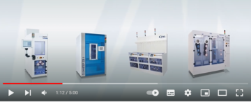
CMT automatic mapping series are fully automatic systems to measure sheet resistance and resistivity with PC remote control or in manual mode.
Typical PC configurations are Windows 7 / 32bit
Depending on application as well as sample size and shape the following series are available:
CMT-100S for wafers up to 180mm or squares up to 160 mm
CMT-2000N for wafers up to 200mm
CMT-2000PV for wafers up to 230mm or squares up to 156 mm
CMT-3000 for glass, LCD, ITO panels up to 600 x 720 mm
CMT-5000 for wafers up to 450mm or squares up to 300 mm
The xyz resolution is +/- 1 mm
The system accuracy of 0.5% is based on a test result with a precision network resistor.
Actual system accuracy is limited by the reference used. For example, a certificated VLSI reference value has an error tolerance of 1.5%
Actual measurement accuracy depends on various factors including environment, contacting condition and probe head, wafer surface, etc.
For example, typical accuracy may include additional tolerances for probe wear-out and repeatability.
IBM/PC compatible with Windows 98/2000/XP versions
The standard remote interface is the RS232 serial communication.
A USB converter can also be used.
Jandel Probes offer the accuracy and perfection of more than 30 years experience. Tip radii and probe spacings are checked by interferometer and video inspection for certainty of accuracy. Spring loadings are checked by electronic force gauge.
Unique Standard specifications include:
1) Upper and lower guides are jewelled
2) Solid tungsten carbide needles for superior durability and accuracy
3) Teflon insulation giving minimum leakage
The best probehead for you depends entirely on your application and what equipment you are using.Contact us with details of the probe you have now and we will let you know the best probe for you. Alternatively, if you wish to make a custom set up, we can help you to identify which probe will work best.
The characteristics needed vary depending on the material being probed. If you contact us we may be able to advise the best characteristics for your samples from past experience. Alternatively, once an order is placed, you have the option of sending us a typical sample of the material you wish to probe and we will test it so that you can be sure to receive the best characteristics for your application.
The unit of measurement when measuring the resistance of a thin film of a material using the four point probe technique. It is equal to the resistance between two electrodes on opposite sides of a theoretical square. The size of the square is unimportant and so strictly the measurement is in ohms, however ohms/square distinguishes measurement of a thin sheet from measurement of, for instance, a wire.
The unit of measurement when measuring the bulk or volume resistivity of thick or homogeneous materials such as bare silicon wafers or silicon ingots, using the four point probe technique.
The term Ohms.cm (Ohms centimeter) refers to the measurement of the “bulk” or “volume” resistivity of a semi-conductive material. Ohms.cm is used for measuring the conductivity of a three dimensional material such as a silicon ingot or a thick layer of a material. The term “Ohms-per- square” is used when measuring sheet resistance, i.e., the resistance value of a thin layer of a semi-conductive material.
The equations for calculating bulk resistivity are different from those used to calculate sheet resistance, however, if the sheet resistance is known, bulk resistivity can be calculated by multiplying the sheet resistance in Ohms-per- square by the thickness of the material in centimeters.
To perform rapid, non-destructive electrical characterization of non-metallized planar semiconductors:
SiC, GaAs, 2DEG, GaN, InP, CdS, InSb, etc.
To substitute alternative methods which take several hours and require detailed metallization.
– characterization of thin epitaxial layers grown on silicon.
– Thin-film characterization screening tool to conduct rapid integrity tests on various substrate surfaces.
Mercury Probes can be connected to C-V plotters, curve tracers, doping profilers, computerized semiconductor measurement systems, CSM-WIN
Resistance can be measured on thin films composed of any material that does not react with mercury.
Metals, semiconductors, oxides, and chemical coatings may be measured successfully.
Mercury Probes can measure oxidized Silicon wafers or bare Silicon wafers
For MOS devices a darkbox is available to prevent light interference.
A mercury probe can be safely used in the usual laboratory or production environment.
Platform measurements confirmed less than standard Mercury concentration of 0.05mg/m3.
Areas surrounding the Mercury storage containers may be higher than standard Mercury concentration so good ventilation is recommended for storage and replacement.
The Mercury probe provides the following inherent safety features:
1) No Mercury is applied without a loaded wafer
2) The automatic PURGE position passage assures removal of the Hg on the platform
3) A darkbox option is available to contain potential Mercury droplets in a confined area
4) The Mercury probe system eliminates air exposure of Mercury in the OFF position
5) A Mercury spill kit is available
6) A Vapor filter option is available
The system is delivered with a complete set of manuals and software.
– Programs to setup and zero the cap meter
– Utilities to calibrate the contact area and stray capacitance
– Utilities for system parameters and system operation.
A comprehensive on-screen HELP function provides specific program information about all program functions, measurement suggestions, technical information, and references.
The MDC C-V and I-V systems provide comprehensive coverage of C-V and / or I-V characterizations through a variety of probes, test equipment and PC software control (CSM/Win).
Specific reasons for using MDC C-V or I-V solutions include:
-Menu-driven operation
-Test Recipes can be saved and edited
-Storage and Recall possibility of complete data sets in all programs
-Storage of Data Summaries in Production Programs
-Comprehensive, single-screen reports of test results
-Overlay plotting of multiple data sets
-Limits checking of test results
-Series Resistance Correction
-Temperature compensation of all measurements
MOS production C-V measurements with or w/o bias-temperature stress with correction of series resistance effects.
MOS ENGINEERING TESTS: MOS C-V and Conductance-Voltage plotting. Advanced features such as theoretical MOS C-V curve generation and Dit computation. Capacitance-Time measurements to determine substrate lifetime with Zerbst analysis. Doping profiling of sub-oxide regions. Thin oxide analysis using the Ricco method. Additional analyses: quantum effects and polysilicon depletion.
JUNCTION TESTS: special adaptive C-V data gathering and analyses for doping and resistivity profiles as well as junction series resistance and built-in potential.
On screen utilities to average doping and resistivity profiles.
VARIABLE FREQUENCY MOS C-V TESTS: to measure MOS device capacitance and conductance as a function of frequency and perform associated analyses to plots Interface Trap Density versus bandgap position using the Conductance-Frequency technique.
MULTIPLE FREQUENCY C-V TESTS: additional software to measure and plot a family of C-V and G-V curves as a function of measurement frequency.
QUASI-STATIC / Dit TEST: automatic data gathering of quasi-static or high frequency C-V plots and associated analyses to plot interface trap density. Analyses including quantum effects and polysilicon depletion.
GOI TESTS (hardware dependent): additional software to measure gate oxide integrity using forced, ramped, or pulsed voltage and current sources. Data presentation histograms, TDDB plots, Weibull plots.
I-V TESTS: additional software to measure & plot current voltage characteristics of junction and MIS structures and oxide breakdown tests.
THIN OXIDE PROGRAMS: measure and analyze thin oxides. Frequency-Shifting data gathering allows accurate measurement of thin oxide C-V plots in the presence of leakage.
The CVC Analysis functions analyze and model C-V plots affected by quantum effects and polysilicon depletion effects.
Depending on characterization needs various combinations with Keysight Technologies or Keithley equipment as well as MDC probes and software can be configured to custom specifications.
The system is delivered with a complete set of manuals and software.
The SYSTEM SETUP software includes:
– programs to setup and zero the cap meter.
– utilities to choose system parameters like default temp, and material parameters.
– utilities for checking system operation.
A comprehensive on-screen HELP function provides specific program information about all program functions, measurement suggestions, technical information, and references.
Four Point Probe Resistivity Measurement
CMT automatic mapping series are fully automatic systems to measure sheet resistance and resistivity with PC remote control or in manual mode.
Typical PC configurations are Windows 7 / 32bit
Depending on application as well as sample size and shape the following series are available:
CMT-100S for wafers up to 180mm or squares up to 160 mm
CMT-2000N for wafers up to 200mm
CMT-2000PV for wafers up to 230mm or squares up to 156 mm
CMT-3000 for glass, LCD, ITO panels up to 600 x 720 mm
CMT-5000 for wafers up to 450mm or squares up to 300 mm
The xyz resolution is +/- 1 mm
The system accuracy of 0.5% is based on a test result with a precision network resistor.
Actual system accuracy is limited by the reference used. For example, a certificated VLSI reference value has an error tolerance of 1.5%
Actual measurement accuracy depends on various factors including environment, contacting condition and probe head, wafer surface, etc.
For example, typical accuracy may include additional tolerances for probe wear-out and repeatability.
IBM/PC compatible with Windows 98/2000/XP versions
The standard remote interface is the RS232 serial communication.
A USB converter can also be used.
Jandel Probes offer the accuracy and perfection of more than 30 years experience. Tip radii and probe spacings are checked by interferometer and video inspection for certainty of accuracy. Spring loadings are checked by electronic force gauge.
Unique Standard specifications include:
1) Upper and lower guides are jewelled
2) Solid tungsten carbide needles for superior durability and accuracy
3) Teflon insulation giving minimum leakage
The best probehead for you depends entirely on your application and what equipment you are using.Contact us with details of the probe you have now and we will let you know the best probe for you. Alternatively, if you wish to make a custom set up, we can help you to identify which probe will work best.
The characteristics needed vary depending on the material being probed. If you contact us we may be able to advise the best characteristics for your samples from past experience. Alternatively, once an order is placed, you have the option of sending us a typical sample of the material you wish to probe and we will test it so that you can be sure to receive the best characteristics for your application.
The unit of measurement when measuring the resistance of a thin film of a material using the four point probe technique. It is equal to the resistance between two electrodes on opposite sides of a theoretical square. The size of the square is unimportant and so strictly the measurement is in ohms, however ohms/square distinguishes measurement of a thin sheet from measurement of, for instance, a wire.
The unit of measurement when measuring the bulk or volume resistivity of thick or homogeneous materials such as bare silicon wafers or silicon ingots, using the four point probe technique.
The term Ohms.cm (Ohms centimeter) refers to the measurement of the “bulk” or “volume” resistivity of a semi-conductive material. Ohms.cm is used for measuring the conductivity of a three dimensional material such as a silicon ingot or a thick layer of a material. The term “Ohms-per- square” is used when measuring sheet resistance, i.e., the resistance value of a thin layer of a semi-conductive material.
The equations for calculating bulk resistivity are different from those used to calculate sheet resistance, however, if the sheet resistance is known, bulk resistivity can be calculated by multiplying the sheet resistance in Ohms-per- square by the thickness of the material in centimeters.
To perform rapid, non-destructive electrical characterization of non-metallized planar semiconductors:
SiC, GaAs, 2DEG, GaN, InP, CdS, InSb, etc.
To substitute alternative methods which take several hours and require detailed metallization.
– characterization of thin epitaxial layers grown on silicon.
– Thin-film characterization screening tool to conduct rapid integrity tests on various substrate surfaces.
Mercury Probes can be connected to C-V plotters, curve tracers, doping profilers, computerized semiconductor measurement systems, CSM-WIN
Resistance can be measured on thin films composed of any material that does not react with mercury.
Metals, semiconductors, oxides, and chemical coatings may be measured successfully.
Mercury Probes can measure oxidized Silicon wafers or bare Silicon wafers
For MOS devices a darkbox is available to prevent light interference.
A mercury probe can be safely used in the usual laboratory or production environment.
Platform measurements confirmed less than standard Mercury concentration of 0.05mg/m3.
Areas surrounding the Mercury storage containers may be higher than standard Mercury concentration so good ventilation is recommended for storage and replacement.
The Mercury probe provides the following inherent safety features:
1) No Mercury is applied without a loaded wafer
2) The automatic PURGE position passage assures removal of the Hg on the platform
3) A darkbox option is available to contain potential Mercury droplets in a confined area
4) The Mercury probe system eliminates air exposure of Mercury in the OFF position
5) A Mercury spill kit is available
6) A Vapor filter option is available
The system is delivered with a complete set of manuals and software.
– Programs to setup and zero the cap meter
– Utilities to calibrate the contact area and stray capacitance
– Utilities for system parameters and system operation.
A comprehensive on-screen HELP function provides specific program information about all program functions, measurement suggestions, technical information, and references.
The MDC C-V and I-V systems provide comprehensive coverage of C-V and / or I-V characterizations through a variety of probes, test equipment and PC software control (CSM/Win).
Specific reasons for using MDC C-V or I-V solutions include:
-Menu-driven operation
-Test Recipes can be saved and edited
-Storage and Recall possibility of complete data sets in all programs
-Storage of Data Summaries in Production Programs
-Comprehensive, single-screen reports of test results
-Overlay plotting of multiple data sets
-Limits checking of test results
-Series Resistance Correction
-Temperature compensation of all measurements
MOS production C-V measurements with or w/o bias-temperature stress with correction of series resistance effects.
MOS ENGINEERING TESTS: MOS C-V and Conductance-Voltage plotting. Advanced features such as theoretical MOS C-V curve generation and Dit computation. Capacitance-Time measurements to determine substrate lifetime with Zerbst analysis. Doping profiling of sub-oxide regions. Thin oxide analysis using the Ricco method. Additional analyses: quantum effects and polysilicon depletion.
JUNCTION TESTS: special adaptive C-V data gathering and analyses for doping and resistivity profiles as well as junction series resistance and built-in potential.
On screen utilities to average doping and resistivity profiles.
VARIABLE FREQUENCY MOS C-V TESTS: to measure MOS device capacitance and conductance as a function of frequency and perform associated analyses to plots Interface Trap Density versus bandgap position using the Conductance-Frequency technique.
MULTIPLE FREQUENCY C-V TESTS: additional software to measure and plot a family of C-V and G-V curves as a function of measurement frequency.
QUASI-STATIC / Dit TEST: automatic data gathering of quasi-static or high frequency C-V plots and associated analyses to plot interface trap density. Analyses including quantum effects and polysilicon depletion.
GOI TESTS (hardware dependent): additional software to measure gate oxide integrity using forced, ramped, or pulsed voltage and current sources. Data presentation histograms, TDDB plots, Weibull plots.
I-V TESTS: additional software to measure & plot current voltage characteristics of junction and MIS structures and oxide breakdown tests.
THIN OXIDE PROGRAMS: measure and analyze thin oxides. Frequency-Shifting data gathering allows accurate measurement of thin oxide C-V plots in the presence of leakage.
The CVC Analysis functions analyze and model C-V plots affected by quantum effects and polysilicon depletion effects.
Depending on characterization needs various combinations with Keysight Technologies or Keithley equipment as well as MDC probes and software can be configured to custom specifications.
The system is delivered with a complete set of manuals and software.
The SYSTEM SETUP software includes:
– programs to setup and zero the cap meter.
– utilities to choose system parameters like default temp, and material parameters.
– utilities for checking system operation.
A comprehensive on-screen HELP function provides specific program information about all program functions, measurement suggestions, technical information, and references.
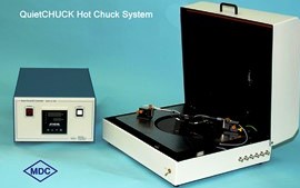
C-V I-V Mercury probe
CMT automatic mapping series are fully automatic systems to measure sheet resistance and resistivity with PC remote control or in manual mode.
Typical PC configurations are Windows 7 / 32bit
Depending on application as well as sample size and shape the following series are available:
CMT-100S for wafers up to 180mm or squares up to 160 mm
CMT-2000N for wafers up to 200mm
CMT-2000PV for wafers up to 230mm or squares up to 156 mm
CMT-3000 for glass, LCD, ITO panels up to 600 x 720 mm
CMT-5000 for wafers up to 450mm or squares up to 300 mm
The xyz resolution is +/- 1 mm
The system accuracy of 0.5% is based on a test result with a precision network resistor.
Actual system accuracy is limited by the reference used. For example, a certificated VLSI reference value has an error tolerance of 1.5%
Actual measurement accuracy depends on various factors including environment, contacting condition and probe head, wafer surface, etc.
For example, typical accuracy may include additional tolerances for probe wear-out and repeatability.
IBM/PC compatible with Windows 98/2000/XP versions
The standard remote interface is the RS232 serial communication.
A USB converter can also be used.
Jandel Probes offer the accuracy and perfection of more than 30 years experience. Tip radii and probe spacings are checked by interferometer and video inspection for certainty of accuracy. Spring loadings are checked by electronic force gauge.
Unique Standard specifications include:
1) Upper and lower guides are jewelled
2) Solid tungsten carbide needles for superior durability and accuracy
3) Teflon insulation giving minimum leakage
The best probehead for you depends entirely on your application and what equipment you are using.Contact us with details of the probe you have now and we will let you know the best probe for you. Alternatively, if you wish to make a custom set up, we can help you to identify which probe will work best.
The characteristics needed vary depending on the material being probed. If you contact us we may be able to advise the best characteristics for your samples from past experience. Alternatively, once an order is placed, you have the option of sending us a typical sample of the material you wish to probe and we will test it so that you can be sure to receive the best characteristics for your application.
The unit of measurement when measuring the resistance of a thin film of a material using the four point probe technique. It is equal to the resistance between two electrodes on opposite sides of a theoretical square. The size of the square is unimportant and so strictly the measurement is in ohms, however ohms/square distinguishes measurement of a thin sheet from measurement of, for instance, a wire.
The unit of measurement when measuring the bulk or volume resistivity of thick or homogeneous materials such as bare silicon wafers or silicon ingots, using the four point probe technique.
The term Ohms.cm (Ohms centimeter) refers to the measurement of the “bulk” or “volume” resistivity of a semi-conductive material. Ohms.cm is used for measuring the conductivity of a three dimensional material such as a silicon ingot or a thick layer of a material. The term “Ohms-per- square” is used when measuring sheet resistance, i.e., the resistance value of a thin layer of a semi-conductive material.
The equations for calculating bulk resistivity are different from those used to calculate sheet resistance, however, if the sheet resistance is known, bulk resistivity can be calculated by multiplying the sheet resistance in Ohms-per- square by the thickness of the material in centimeters.
To perform rapid, non-destructive electrical characterization of non-metallized planar semiconductors:
SiC, GaAs, 2DEG, GaN, InP, CdS, InSb, etc.
To substitute alternative methods which take several hours and require detailed metallization.
– characterization of thin epitaxial layers grown on silicon.
– Thin-film characterization screening tool to conduct rapid integrity tests on various substrate surfaces.
Mercury Probes can be connected to C-V plotters, curve tracers, doping profilers, computerized semiconductor measurement systems, CSM-WIN
Resistance can be measured on thin films composed of any material that does not react with mercury.
Metals, semiconductors, oxides, and chemical coatings may be measured successfully.
Mercury Probes can measure oxidized Silicon wafers or bare Silicon wafers
For MOS devices a darkbox is available to prevent light interference.
A mercury probe can be safely used in the usual laboratory or production environment.
Platform measurements confirmed less than standard Mercury concentration of 0.05mg/m3.
Areas surrounding the Mercury storage containers may be higher than standard Mercury concentration so good ventilation is recommended for storage and replacement.
The Mercury probe provides the following inherent safety features:
1) No Mercury is applied without a loaded wafer
2) The automatic PURGE position passage assures removal of the Hg on the platform
3) A darkbox option is available to contain potential Mercury droplets in a confined area
4) The Mercury probe system eliminates air exposure of Mercury in the OFF position
5) A Mercury spill kit is available
6) A Vapor filter option is available
The system is delivered with a complete set of manuals and software.
– Programs to setup and zero the cap meter
– Utilities to calibrate the contact area and stray capacitance
– Utilities for system parameters and system operation.
A comprehensive on-screen HELP function provides specific program information about all program functions, measurement suggestions, technical information, and references.
The MDC C-V and I-V systems provide comprehensive coverage of C-V and / or I-V characterizations through a variety of probes, test equipment and PC software control (CSM/Win).
Specific reasons for using MDC C-V or I-V solutions include:
-Menu-driven operation
-Test Recipes can be saved and edited
-Storage and Recall possibility of complete data sets in all programs
-Storage of Data Summaries in Production Programs
-Comprehensive, single-screen reports of test results
-Overlay plotting of multiple data sets
-Limits checking of test results
-Series Resistance Correction
-Temperature compensation of all measurements
MOS production C-V measurements with or w/o bias-temperature stress with correction of series resistance effects.
MOS ENGINEERING TESTS: MOS C-V and Conductance-Voltage plotting. Advanced features such as theoretical MOS C-V curve generation and Dit computation. Capacitance-Time measurements to determine substrate lifetime with Zerbst analysis. Doping profiling of sub-oxide regions. Thin oxide analysis using the Ricco method. Additional analyses: quantum effects and polysilicon depletion.
JUNCTION TESTS: special adaptive C-V data gathering and analyses for doping and resistivity profiles as well as junction series resistance and built-in potential.
On screen utilities to average doping and resistivity profiles.
VARIABLE FREQUENCY MOS C-V TESTS: to measure MOS device capacitance and conductance as a function of frequency and perform associated analyses to plots Interface Trap Density versus bandgap position using the Conductance-Frequency technique.
MULTIPLE FREQUENCY C-V TESTS: additional software to measure and plot a family of C-V and G-V curves as a function of measurement frequency.
QUASI-STATIC / Dit TEST: automatic data gathering of quasi-static or high frequency C-V plots and associated analyses to plot interface trap density. Analyses including quantum effects and polysilicon depletion.
GOI TESTS (hardware dependent): additional software to measure gate oxide integrity using forced, ramped, or pulsed voltage and current sources. Data presentation histograms, TDDB plots, Weibull plots.
I-V TESTS: additional software to measure & plot current voltage characteristics of junction and MIS structures and oxide breakdown tests.
THIN OXIDE PROGRAMS: measure and analyze thin oxides. Frequency-Shifting data gathering allows accurate measurement of thin oxide C-V plots in the presence of leakage.
The CVC Analysis functions analyze and model C-V plots affected by quantum effects and polysilicon depletion effects.
Depending on characterization needs various combinations with Keysight Technologies or Keithley equipment as well as MDC probes and software can be configured to custom specifications.
The system is delivered with a complete set of manuals and software.
The SYSTEM SETUP software includes:
– programs to setup and zero the cap meter.
– utilities to choose system parameters like default temp, and material parameters.
– utilities for checking system operation.
A comprehensive on-screen HELP function provides specific program information about all program functions, measurement suggestions, technical information, and references.
C-V I-V
CMT automatic mapping series are fully automatic systems to measure sheet resistance and resistivity with PC remote control or in manual mode.
Typical PC configurations are Windows 7 / 32bit
Depending on application as well as sample size and shape the following series are available:
CMT-100S for wafers up to 180mm or squares up to 160 mm
CMT-2000N for wafers up to 200mm
CMT-2000PV for wafers up to 230mm or squares up to 156 mm
CMT-3000 for glass, LCD, ITO panels up to 600 x 720 mm
CMT-5000 for wafers up to 450mm or squares up to 300 mm
The xyz resolution is +/- 1 mm
The system accuracy of 0.5% is based on a test result with a precision network resistor.
Actual system accuracy is limited by the reference used. For example, a certificated VLSI reference value has an error tolerance of 1.5%
Actual measurement accuracy depends on various factors including environment, contacting condition and probe head, wafer surface, etc.
For example, typical accuracy may include additional tolerances for probe wear-out and repeatability.
IBM/PC compatible with Windows 98/2000/XP versions
The standard remote interface is the RS232 serial communication.
A USB converter can also be used.
Jandel Probes offer the accuracy and perfection of more than 30 years experience. Tip radii and probe spacings are checked by interferometer and video inspection for certainty of accuracy. Spring loadings are checked by electronic force gauge.
Unique Standard specifications include:
1) Upper and lower guides are jewelled
2) Solid tungsten carbide needles for superior durability and accuracy
3) Teflon insulation giving minimum leakage
The best probehead for you depends entirely on your application and what equipment you are using.Contact us with details of the probe you have now and we will let you know the best probe for you. Alternatively, if you wish to make a custom set up, we can help you to identify which probe will work best.
The characteristics needed vary depending on the material being probed. If you contact us we may be able to advise the best characteristics for your samples from past experience. Alternatively, once an order is placed, you have the option of sending us a typical sample of the material you wish to probe and we will test it so that you can be sure to receive the best characteristics for your application.
The unit of measurement when measuring the resistance of a thin film of a material using the four point probe technique. It is equal to the resistance between two electrodes on opposite sides of a theoretical square. The size of the square is unimportant and so strictly the measurement is in ohms, however ohms/square distinguishes measurement of a thin sheet from measurement of, for instance, a wire.
The unit of measurement when measuring the bulk or volume resistivity of thick or homogeneous materials such as bare silicon wafers or silicon ingots, using the four point probe technique.
The term Ohms.cm (Ohms centimeter) refers to the measurement of the “bulk” or “volume” resistivity of a semi-conductive material. Ohms.cm is used for measuring the conductivity of a three dimensional material such as a silicon ingot or a thick layer of a material. The term “Ohms-per- square” is used when measuring sheet resistance, i.e., the resistance value of a thin layer of a semi-conductive material.
The equations for calculating bulk resistivity are different from those used to calculate sheet resistance, however, if the sheet resistance is known, bulk resistivity can be calculated by multiplying the sheet resistance in Ohms-per- square by the thickness of the material in centimeters.
To perform rapid, non-destructive electrical characterization of non-metallized planar semiconductors:
SiC, GaAs, 2DEG, GaN, InP, CdS, InSb, etc.
To substitute alternative methods which take several hours and require detailed metallization.
– characterization of thin epitaxial layers grown on silicon.
– Thin-film characterization screening tool to conduct rapid integrity tests on various substrate surfaces.
Mercury Probes can be connected to C-V plotters, curve tracers, doping profilers, computerized semiconductor measurement systems, CSM-WIN
Resistance can be measured on thin films composed of any material that does not react with mercury.
Metals, semiconductors, oxides, and chemical coatings may be measured successfully.
Mercury Probes can measure oxidized Silicon wafers or bare Silicon wafers
For MOS devices a darkbox is available to prevent light interference.
A mercury probe can be safely used in the usual laboratory or production environment.
Platform measurements confirmed less than standard Mercury concentration of 0.05mg/m3.
Areas surrounding the Mercury storage containers may be higher than standard Mercury concentration so good ventilation is recommended for storage and replacement.
The Mercury probe provides the following inherent safety features:
1) No Mercury is applied without a loaded wafer
2) The automatic PURGE position passage assures removal of the Hg on the platform
3) A darkbox option is available to contain potential Mercury droplets in a confined area
4) The Mercury probe system eliminates air exposure of Mercury in the OFF position
5) A Mercury spill kit is available
6) A Vapor filter option is available
The system is delivered with a complete set of manuals and software.
– Programs to setup and zero the cap meter
– Utilities to calibrate the contact area and stray capacitance
– Utilities for system parameters and system operation.
A comprehensive on-screen HELP function provides specific program information about all program functions, measurement suggestions, technical information, and references.
The MDC C-V and I-V systems provide comprehensive coverage of C-V and / or I-V characterizations through a variety of probes, test equipment and PC software control (CSM/Win).
Specific reasons for using MDC C-V or I-V solutions include:
-Menu-driven operation
-Test Recipes can be saved and edited
-Storage and Recall possibility of complete data sets in all programs
-Storage of Data Summaries in Production Programs
-Comprehensive, single-screen reports of test results
-Overlay plotting of multiple data sets
-Limits checking of test results
-Series Resistance Correction
-Temperature compensation of all measurements
MOS production C-V measurements with or w/o bias-temperature stress with correction of series resistance effects.
MOS ENGINEERING TESTS: MOS C-V and Conductance-Voltage plotting. Advanced features such as theoretical MOS C-V curve generation and Dit computation. Capacitance-Time measurements to determine substrate lifetime with Zerbst analysis. Doping profiling of sub-oxide regions. Thin oxide analysis using the Ricco method. Additional analyses: quantum effects and polysilicon depletion.
JUNCTION TESTS: special adaptive C-V data gathering and analyses for doping and resistivity profiles as well as junction series resistance and built-in potential.
On screen utilities to average doping and resistivity profiles.
VARIABLE FREQUENCY MOS C-V TESTS: to measure MOS device capacitance and conductance as a function of frequency and perform associated analyses to plots Interface Trap Density versus bandgap position using the Conductance-Frequency technique.
MULTIPLE FREQUENCY C-V TESTS: additional software to measure and plot a family of C-V and G-V curves as a function of measurement frequency.
QUASI-STATIC / Dit TEST: automatic data gathering of quasi-static or high frequency C-V plots and associated analyses to plot interface trap density. Analyses including quantum effects and polysilicon depletion.
GOI TESTS (hardware dependent): additional software to measure gate oxide integrity using forced, ramped, or pulsed voltage and current sources. Data presentation histograms, TDDB plots, Weibull plots.
I-V TESTS: additional software to measure & plot current voltage characteristics of junction and MIS structures and oxide breakdown tests.
THIN OXIDE PROGRAMS: measure and analyze thin oxides. Frequency-Shifting data gathering allows accurate measurement of thin oxide C-V plots in the presence of leakage.
The CVC Analysis functions analyze and model C-V plots affected by quantum effects and polysilicon depletion effects.
Depending on characterization needs various combinations with Keysight Technologies or Keithley equipment as well as MDC probes and software can be configured to custom specifications.
The system is delivered with a complete set of manuals and software.
The SYSTEM SETUP software includes:
– programs to setup and zero the cap meter.
– utilities to choose system parameters like default temp, and material parameters.
– utilities for checking system operation.
A comprehensive on-screen HELP function provides specific program information about all program functions, measurement suggestions, technical information, and references.

