Mercury Probe
Mercury Probe Systems for CV / IV and Sheet Resistance Measurements
Mercury probe systems are used for non-destructive C-V, I-V and sheet resistance measurements in semiconductor R&D, process development and materials evaluation. They provide rapid electrical characterization without permanent metallization or probe card setup, making them well suited for flexible measurement environments and early-stage device analysis. As well as Furnace contaminants monitoring.
MDC Europe supplies mercury probe solutions designed for repeatable measurements, stable contact conditions and efficient integration into laboratory and pilot workflows.
Typical Use Cases
Mercury probe systems are typically used when:
- rapid electrical characterization is required
- samples cannot be permanently metallized
- multiple wafers or materials must be evaluated efficiently
- setup time and measurement flexibility are critical
They are commonly deployed in R&D laboratories, materials screening workflows and process monitoring activities.
Measurement Capabilities
Mercury probe systems support:
Three operating modes:
- Front-Back Contact,
- Dual Front Contact, and
- Front-Back Contact with guard ring.
- Little or no sample preparation required.
- Use with semiconductors and insulators.
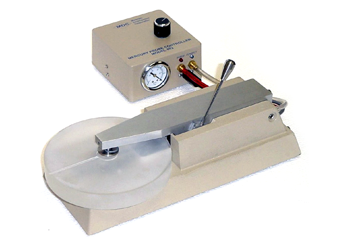
- Single control arm operation.
- Unique purge control insures that clean mercury always contacts the wafer.
- Safe to use because of a novel fail-safe mercury delivery system that is vacuum actuated. No mercury is drawn out of the probe unless a wafer is in place.
- Sturdy construction features a heavy cast aluminum base for years of rugged service
- Comes complete with vacuum pump, cables, control box with vacuum regulator, and a comprehensive operator’s manual.
- Available with sturdy aluminum enclosure for light sensitive measurements.
Mercury Probes Specifications
- Size: 6″ W x 13″ D x 7″ H (15 cm W x 33 cm D x 18 cm H).
- Dot Contact Diameter: Nominally .030″ (760 micrometers). Other sizes available.
- Repeatability of contact area : 1.1 %.
- Area ratio : ring contact : dot contact : 48.6 : 1.
- Contact spacing: Nominally .015″ (400 micrometers).
MDC Europe Expertise
MDC Europe provides mercury probe systems configured for stable, repeatable measurements and supported by strong application expertise. Our solutions are designed to meet the practical requirements of semiconductor R&D and process development environments. Refurbishment of the Mercury Probe is also possible.

Why to Choose Our Products?
- OEM-level refurbishment meeting original specifications
- 30+ years of experience in semiconductor solutions
- Fast European delivery and support
- Comprehensive product portfolio from spares to systems
- Trusted by leading OEMs and research institutes